


The Wiring of The Electronic Sensors
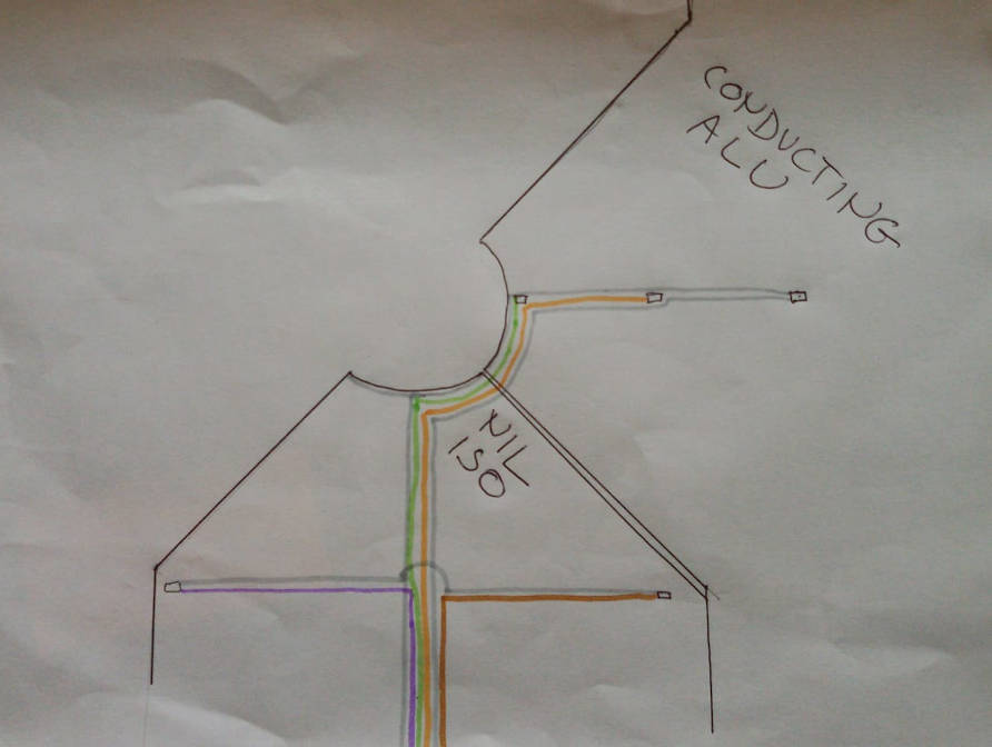 The "NIL ISO" fin (middle of picture) corresponds to an insulating light green
fin and the "CONDUCTING ALU" (to the right in the picture) corresponds to
a conducting aluminium fin. Both fins are mechanically fitted together and
has a machine cut trace to hold the thermic pt500 sensors and it's cabling.
The "NIL ISO" fin (middle of picture) corresponds to an insulating light green
fin and the "CONDUCTING ALU" (to the right in the picture) corresponds to
a conducting aluminium fin. Both fins are mechanically fitted together and
has a machine cut trace to hold the thermic pt500 sensors and it's cabling.
Starting to the far right is a rectangle connected to grey colour cabling.
This symbols the conducting fin peripheral thermic sensor (T1). The upper
grey cable is the earth and it connects to all five rectangular pt500 sensor
symbols in the picture. The lower grey cable is connecting the peripheral
pt500 (T1) to the MCP3208 AD converter of the Dynamic Link Control.
Following the upper grey gable, earth cable, to the left it connects to
the middle thermic sensor (T2) and it's lower orange cable connects to
another channel of the Dynamic Link MCP3208 AD.
Again, following the upper grey gable to the left it connects to the centre
thermic sensor (T3) positioned on the fin closest to the Revolving Shutter
shaft. The centre sensor lower green cable connects to a third channel of
the MCP3208 AD.