

Verifying thermistor chain and conducting hot fin heat transport
 Set up:
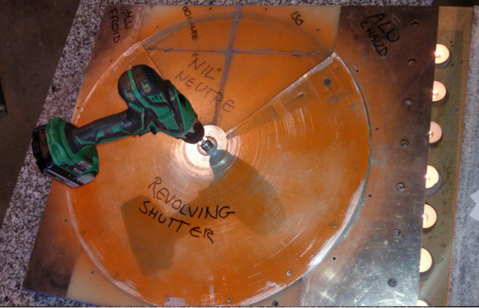
Open horizontal GREC consisting of BottomLayer plate with boundary Shells,
MidLayer with 10 thermistors type pt500 (see layout sketch below) and a
two disk Revolving Shutter (RS) parked in a position with the Work Generating
Volume (WGV) opening standing still in the "Nil-position" paired with the
Conducting Cold Fin.
Using some IKEA Värmeljus candles under the hot fins and triggering
measurements manually by passing a hall-sensor over the position magnet
in the Revolving Shutter. The DynamicLink software logged something like
40 readings during 2385 seconds i.e. roughly 40 readings during 40 minutes
and is presented below as a graph.

The graph shows that the heat travels steady in the aluminium
of the heat conducting fin from the peripheral heat sensor T1
(called "2(7)" with a gray line) to the middle T2 sensor (named
"2(6)" that has an orange line) and the heat finally reaches the
third sensor T3, a green line named "2(5)". T3 is at the end of
the conducting aluminium fin on the warm side close to the shaft
in the middle of the GREC. You can see the sensor layout and colours
in this picture:

The Graph also shows an almost constant temperature in the cold
conducting fin which is totally correct since its only contact
is air with ambient temperature. (Remember the Revolving Shutter is
parked with its work Generating Volume above one neutral "nil" fin.)
The graph shows that the air above the hot fin is heated and travels in
the gap between the fins and the Revolving Shutter and heats up the two
heat sensors (violette and brown lines) of the covered paired insulating
"nil" fin that will measure the air temperature of the passing Work
Generating Volume. The other insulating "nil" fin temperature
sensors show ambient air temperature which is absolutely correct
since it has the open Work Generating Volume filled with ambient
air parked above its two heat sensors.
Conclusion:
- All the heat sensors in the thermistor chain works.
- The heat sensors in the conducting fins measures the temperature
of the metal of the fin proving its heat transport.
- The thermistors in the neutral isolating "nil" fins measures
the temperature of the air above the fins.
Note:
The the MCP3208 A/D circuits reads the analog pt500 termistors
and delivers a digital value to the DynamicLink program. There are
some very random fluctuations in the digital values. Minimising
these fluctuations will save us a lot of work in analysing future
results.


